ZB4-BW343
ActiveHarmony XB4 Illuminated Red Push Button 24V LED

Illuminated red flush push button with integrated 24V LED for Schneider Harmony XB4 series. 22mm cutout, IP66 rated. Visual confirmation of stop/fault state.
Common Applications
Illuminated red push button that lights up to confirm the machine is stopped or a fault is present. The red LED provides clear visual status — lit means the stop circuit is active or an alarm condition exists. Common on packaging lines, conveyor systems, and CNC machine auxiliary panels where operators need immediate confirmation that the stop command was received. Pairs with the green illuminated ZB4-BW333 for a matched start/stop set. Uses a 1NC contact with ZB4-BZ102 block, so the circuit breaks on press — standard fail-safe wiring for stop functions.
Specifications
|
Actuator Shape
The physical shape of the pressable surface.
|
Round
|
|
Actuator Type
The button head style. Flush sits level with the bezel (prevents accidental presses). Extended protrudes for easy access.
|
Flush
|
|
Certifications
Third-party safety certifications. UL = required for US NEC installations. CE = EU compliance. CSA = Canadian standards.
|
UL, CSA, CE
|
|
Color
Button/actuator color. Green = start/go, Red = stop/emergency, Yellow = caution, Blue = reset (per IEC 60204-1).
|
Red
|
|
Contact Configuration
Normally Closed — circuit is on until you press. Standard for stop/emergency functions. Wire in series with safety circuits.
|
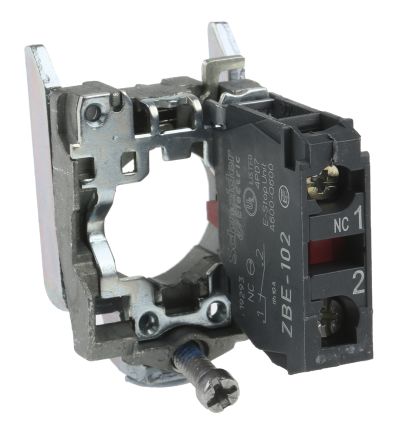
1NC (with ZB4-BZ102)
|
|
Cutout Diameter
The hole size you drill in your panel to mount this button. 22mm is the most common industrial standard worldwide.
|
22mm
|
|
Illuminated
|
Yes
|
|
IP Rating
IP66: Dust-tight and withstands powerful water jets from any direction. Standard for outdoor and washdown applications.
|
IP66
|
|
LED Color
Color of the built-in LED indicator light.
|
Red
|
|
LED Voltage
The voltage required for the built-in LED. Must match your control circuit voltage (typically 24V DC or 230V AC).
|
24V AC/DC
|
|
Material
The bezel/body material. Metal bezels are more durable in harsh environments. Plastic is lighter and cheaper.
|
Metal
|
|
Mechanical Life
How many press cycles before mechanical failure. Higher is better — 10M cycles at 100 presses/day = 274 years.
|
10,000,000 cycles
|
|
Mounting Type
How the button attaches to the panel. Panel mount is standard — installs through a cutout from the front.
|
Panel
|
|
Max Operating Temp
Highest temperature the button is rated to operate in.
|
70°C
|
|
Min Operating Temp
Lowest temperature the button is rated to operate in.
|
-25°C
|
Specs with this icon are linked to the manufacturer's original source page
You'll Also Need
This is a modular component. For a complete assembly, you may also need:
Compatible Alternatives
These products are functionally equivalent cross-references from other manufacturers.
Installation Quick Reference
Panel cutout: 22mm. Insert from the front of the panel, secure with mounting nut from behind (tighten to 2-3 Nm).
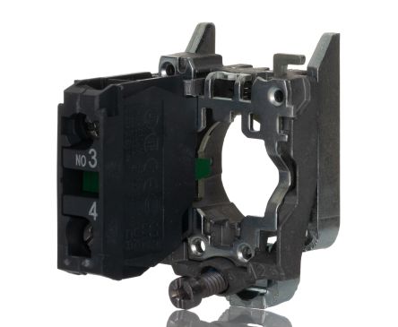
Contact block: Snap or screw the contact block onto the rear of the button body. Ensure the contact block orientation matches the wiring diagram — NO terminals are usually marked.
Wiring: Use 0.5-2.5mm² stranded wire with ferrules. Tighten screw terminals to 0.8 Nm. Test the button function before energizing the circuit.
Dimensions
Wiring Diagram
Troubleshooting
Button doesn't respond when pressed
Check the contact block first — it's the most common failure point. Test continuity across the NO or NC terminals with a multimeter. If no click is felt, the return spring in the head may be broken.
Works intermittently
Contact block contacts are pitted or burned. Replace the contact block — don't try to file the contacts. Check if the rated cycle count has been exceeded.
Button feels mushy or doesn't click
The spring return mechanism in the button head is worn. Replace the head. The contact block can usually be reused if it tests OK.

Where to Buy
Price range
$1.88 — $17.18
across 4 distributors
Quick Specs
- Actuator Shape
- Round
- Actuator Type
- Flush
- Certifications
- UL, CSA, CE
- Color
- Red
- Contact Configuration
- 1NC (with ZB4-BZ102)
What People Are Saying
“Solid button for panel builds. Schneider Electric Harmony XB4 series is well-proven in the field. Standard 22mm mounting means easy replacement if needed.”
Learn More
Data Sources
Specifications and product data sourced from the following references.
