3SU18510NB002AA2
ActiveSiemens 3SU18510NB002AA2
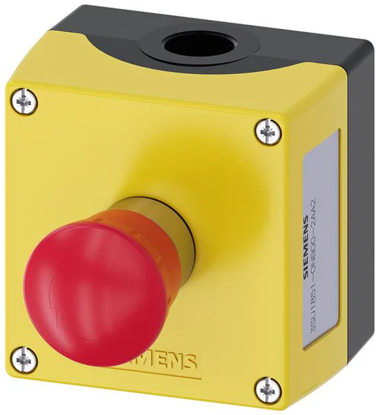
Emergency Stop Switches / E-Stop Switches ENC METAL, EMERG STOP TWIST-RELEASE,2NC
Research Notes
1. What this is
3SU18510NB002AA2 is a Siemens device — series not recognized.
2. Part-number decode
- Series: Siemens (series not recognized)
3. Compatibility & ordering
Siemens command switches are modular IEC-style panel devices. Match by size, function (pushbutton/selector/indicator/E-stop), color, illumination, and contact blocks; cross-reference to Schneider Harmony, Allen-Bradley 800F, IDEC HW, or Eaton M22 by the same attributes if needed.
4. Data-quality note
The exact Siemens series/configuration could not be confidently decoded from this part number. Kept and documented; flagged needs-verification.
5. Sources
- Siemens LV1 catalog / SIRIUS ACT (3SU) & Class 52 selection data (siemens.com)
- Siemens Industry Mall — search the exact part/material number
- Distributor listing (Mouser / Newark) — search the exact part number
1 source
- Siemens Industry Mall — 3SU18510NB002AA2 — siemens.com
About the SIRIUS ACT (3SU1) range
Applies to every part of the range, not only the 3SU18510NB002AA2.
What the range is
SIRIUS ACT (3SU1) is Siemens' modular range of 22 mm pushbuttons, selector switches, key switches, emergency stops and indicator lights. It comes in three design lines:
- 3SU1.0: plastic front ring, black, 22 mm
- 3SU1.5: shiny metal, 22 mm
- 3SU1.6: matte metal with a flat front, 30 mm
From October 2017 it replaced the older 3SB3, 3SB1 and 3SF5 ranges, which were gone from stock by late 2019. Siemens publishes a conversion list from the old codes (support entry 109756490). The 16 mm 3SB2 is a separate range.
How the article numbers work
Siemens article numbers have the form 3SU1 ●●● – ● ●●●● – ●●●●. Taking 3SU1100-0AB20-1BA0, a red flat pushbutton with 1 NO:
| Position | Meaning | Values |
|---|---|---|
| 1st digit after 3SU1 | device type | 0 actuator or indicator only, 1 complete unit, 2 compact unit, 4 module, 5 holder, 8 enclosure, 9 accessory |
| 2nd | front ring | 0 plastic black, 5 metal shiny, 6 metal matte |
| 3rd | illumination | 0 non-illuminated, 1 illuminated |
| after the dash | actuator type | 0 pushbutton, 1 mushroom / E-stop, 2 selector switch, 3 twin / toggle, 4–5 key switch, 6 indicator light or buzzer, 7 coordinate switch |
| letters | design and function | e.g. A flat, B momentary |
| two digits | colour | 00 amber, 10 black, 20 red, 30 yellow, 40 green, 50 blue, 60 white, 70 clear |
| last block | connection and contacts | 1 screw / 3 spring-loaded terminals; then e.g. A no contact, B 1 NO, C 1 NC; marking (A none, C "I", D "O"); last digit 2 = ATEX |
The most common mistake: an actuator alone (3SU10…, 3SU15…, 3SU16…, ending -0AA0) has no holder and no contacts. To make it work you add a holder (3SU1500-0AA10-0AA0 plastic, 3SU1510-0AA10-0AA0 metal, 3SU1550-0AA10-0AA0 universal) and contact modules. A complete unit (3SU11…) includes both.
Selector switches
Function letters (short handle B, long handle C), on actuators and on complete units:
- BF: 2 positions, latching 90°
- BC: 2 positions, spring return from centre to left
- BL: 3 positions, latching 2 × 45°
- BM: 3 positions, spring return from both sides to centre
- BP / BN: spring return from the left, latching right / latching left, return from the right
- GL: 3 positions latching, lockable with padlocks
For example, 3SU1052-2BL10-0AA0 is a shiny metal 3-position latching selector actuator; it needs a holder and contacts.
Contact modules (front-plate mounting)
| Module | Contacts |
|---|---|
| 3SU1400-1AA10-1BA0 | 1 NO |
| 3SU1400-1AA10-1CA0 | 1 NC (positively driven) |
| 3SU1400-1AA10-1DA0 | 2 NO |
| 3SU1400-1AA10-1EA0 | 2 NC |
| 3SU1400-1AA10-1FA0 | 1 NO + 1 NC |
| 3SU1400-1AA10-1HA0 | 1 NC with installation supervision (for E-stops: opens if the module comes off the holder) |
In these codes, -3… instead of -1… means spring-loaded terminals. Ratings: 10 A thermal; AC-15 6 A at 24–230 V and 3 A at 400 V; DC-13 3 A at 24 V and 0.7 A at 110 V. Mechanical life is 10 million operations. The contacts are slow-action, reliable down to 5 V / 1 mA, and suitable for PLC inputs.
Ratings for the range (Siemens catalogue IC 10, 2026)
- IP66, IP67, IP69 (IP69K) for most actuators (quadruple pushbuttons IP65/IP66)
- Operating temperature −25 to +70 °C (storage −40 to +80 °C). Schneider's Harmony is rated to −40 °C.
- Mechanical life: momentary pushbuttons 10 million operations, latching pushbuttons 500,000, selector switches 1 million, E-stops 300,000
- Shock 15 g; vibration 5 g (10–500 Hz); standards IEC 60947-1 and IEC 60947-5-1 (IEC 60947-5-5 for E-stops)
Installing
Hole 22.3 mm (+0.4 mm; Siemens calls the size 22.5 mm), panel 1–6 mm, with holes at least 30 mm apart side by side and 40 mm one above the other when using 3-position holders (40 × 40 mm with 4-position holders). The holder clips on from behind and is clamped by one screw at the top, tightened with a size 2 screwdriver to 1.0–1.2 N·m; no special tool is needed. Holders come preset for a panel of about 4.5 mm, so adjust the screw first on a thicker panel. Label holders and protective caps reduce the allowed panel thickness. Metal holders on a metal panel ground the actuator through the screw tip.
Buying notes
- Check that you are buying a complete unit (3SU11…/3SU115…) and not just the actuator, unless you have holders and contact modules.
- Colour comes from the code: …0AB20… is red and …0AB60… is white. Shops sometimes mis-decode it; trust the two digits before the last dash.
- Older 3SB3 parts are discontinued. Use Siemens' conversion list to find the 3SU1 replacement; it usually needs a holder and contact module as well.
- Problems in use: we found no recurring failure pattern in the sources we could read.
5 sources
- Catalog IC 10 · 2026, chapter 13: Commanding and signaling devices (SIRIUS ACT) — Siemens
- System Manual SIRIUS ACT 3SU1 pushbuttons and signaling devices — Siemens
- Conversion list for the phase-out of 3SB3/3SB1/3SF5 to SIRIUS ACT (3SU1) — Siemens Industry Support
- SIRIUS 3SB3/3SB1/3SF5 phase-out (began October 2017) — Siemens Industry Mall
- SIRIUS ACT - Performance in Action (3SB3 not available after October 2019) — Siemens / RS
Specifications
|
Enriched by
|
siemens-decoder-2026-08-12
|
|
Lead time
|
29 Days
|
|
Manufacturer series
|
Siemens (series not recognized)
|
|
Mouser part number
|
982-3SU18510NB002AA2
|
|
Pn status
|
needs-verification
|
|
Rohs status
|
RoHS Compliant
|
|
Series description
|
Siemens control/switch device — exact series/config could not be decoded from this part number; kept and flagged for verification rather than guessed
|
Installation Quick Reference
Panel cutout: 22mm. Mount with the yellow backing plate visible (required by EN/ISO 13850).
Wiring: Wire NC contacts in series with the safety relay input channels. Use dual-channel wiring for SIL 3 / PLe applications. Never wire directly to a motor contactor.
Testing: Press the e-stop and verify the machine stops within the required time. Test the reset mechanism. Repeat monthly per EN/ISO 13850.
Dimensions
Troubleshooting
E-stop won't reset (twist/pull doesn't release)
Check for debris in the mechanism. For twist-release: turn clockwise 45-90 degrees. For push-pull: pull straight out firmly. If the mechanism is stuck, the internal latch may be damaged — replace the entire head assembly.
Machine doesn't stop when e-stop is pressed
Critical safety issue. Immediately lock out the machine. Check wiring — NC contacts must be in series with the safety relay. Verify the safety relay is functioning. A broken wire in an NC circuit should cause a stop, so check for a wiring bypass.
Safety relay faults after e-stop reset
The safety relay detects a cross-fault between the two monitoring channels. Check that both NC contacts on the e-stop are switching simultaneously. One contact may be welded closed — replace the contact block.
Where to Buy
Quick Specs
- Enriched by
- siemens-decoder-2026-08-12
- Lead time
- 29 Days
- Manufacturer series
- Siemens (series not recognized)
- Mouser part number
- 982-3SU18510NB002AA2
- Pn status
- needs-verification


